6400 SERIES
6400 SERIES PRECISION COMPONENT ANALYZER
Overview
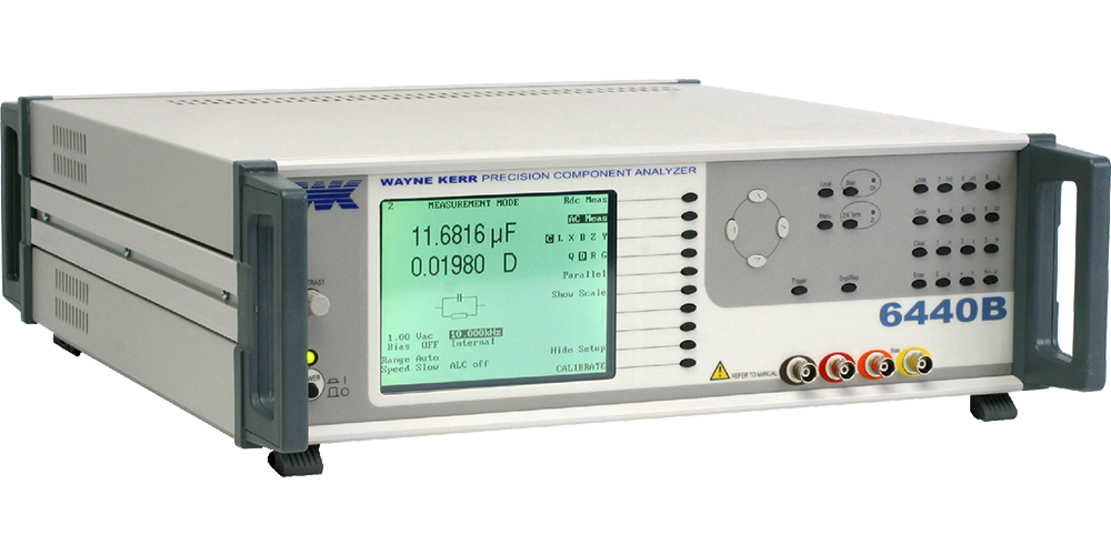
The 6430B and 6440B Precision Component Analyzers provide thorough and accurate testing of any passive component to high resolution. In particular, for capacitor manufacturers, the instruments provide capabilities for both fast automatic production testing and complete design characterisation. Users include designers of passive components, manufacturing test, designing and testing materials as well as circuit designers who are evaluating component characteristics.
The resonant frequency can be automatically calculated for any component together with its equivalent series or parallel circuit at that frequency. Both instruments are designed for high performance testing of components, with a basic accuracy of 0.02%, at a low price. 6430B is the entry level instrument covering to 500 kHz whilst the fully featured 6440B covers to 3 MHz.
To evaluate a component performance at high speed over a specified range of frequencies, multi frequency mode is used. In this mode the operator decides which parameter is to be measured and at what frequencies. The 6430B and 6440B does the rest, creating an easy to read table on the large LCD display. Each test can have a simple Pass/Fail display.
Fast automatic multi-frequency production testing of capacitors
The 6430B and 6440B deliver fast automatic testing of capacitors in a production environment. The user is able to select measurements from any of the instruments range and perform up to eight different tests on each component. Tolerance bins can be selected for each of the tests. The instrument selects the overall bin after completing all the tests. The measured results can be output over the GPIB or to a printer. The test sequence is triggered by external input, GPIB or the front panel. Once the test sequence is complete the bin is selected and the measured data is made available on the GPIB. This process takes place at very high speed allowing a dual frequency test to be completed in approximately 180 ms. Pass/Fail data in statistical form is available to the user and can be viewed on the LCD display, printed to a local printer or exported over the GPIB.
Protection against charged capacitors
High precision measuring instruments can be sensitive to charged capacitors and if connected can lead to costly repairs and unacceptable downtime. Wayne Kerr Electronics have identified this problem and developed a solution that protects the test equipment from charged capacitors. In this event, the protection unit blows fuses, which can be easily and cheaply replaced, whilst the test equipment remains unharmed and continues to provide reliable accurate performance. The protection unit will protect the test equipment from up to 25 Joules of charged energy.

Overload Protection Unit 1J1100
Key Features
- Fast automatic capacitor testing
- High measurement accuracy on dissipation factor
- Fast measurement speed
- 0.02% basic measurement adccuracy
- Comprehensive measurement functions, Graphical sweep on all measurement functions
- Characterize components to 3 MHz
- Large LCD Display and intuitive user interface
- Unbeatable price
Technical Specification
| Measurement Function | Any of the following parameters can be measured and displayed: Inductance (L), impedance (Z), DC resistance (Rdc) and capacitance (C) Series or Parallel Equivalent Circuit C+R, C+D, C+Q, L+R, L+Q Series equivalent circuit only X+R, X+D, X+Q Parallel equivalent circuit only C+G, B+G, B+D, B+Q Polar Form Z + Phase Angle, Y + Phase Angle |
| Frequency Range | 6430B – 20 Hz to 500 kHz > 1000 steps ( > 1500 steps with analysis option fitted) 6440B – 20 Hz to 3 MHz > 1800 steps |
| Drive Level(Rdc) | 100 mV or 1 V with 100 Ω source resistance |
| Internal DC Bias Supply | 2 V with rapid charge capacitor bias |
| DC Bias Voltage (External) | External supply of up to ±60 V may be connected via rear panel |
| Measurement Speeds | 4 speeds selectable Up to 20 measurements per second for test frequencies ≧100 Hz |
| Measurement Ranges | R, Z 0.01 mΩ to > 2 GΩ G, Y 1 nS to > 2 kS L 0.1 nH to > 2 kH C 1 fF to > 1 F D 0.00001 to >1000 Q 0.00001 to >1000 Rdc 0.1 mΩ to > 10 MΩ |
| Accuracy | L/C ±0.05% R ±0.02% Q ± 0.05 %(Q + 1/Q) D ±0.0002(1+ D2) Rdc ± 0.1%Accuracy varies with component range measurement speed and frequency |
| Input Specification | Power supply 230 V AC ±10% or 115 V AC ±10% (selectable) Mains frequency 50/60 Hz 150VA maximum consumption |
| Display | High contrast monochrome LCD 320 x 240 dot with CFL back lighting Visible area 115 x 86mm Viewing angle 45° |
| Measurement Connections | 4 front panel BNC sockets 4-wire (Kelvin) measurements with screen at ground potential |